Index
1. Introduction2. Placing objects in the TE, object descriptions
2.1 Internal objects
2.2 object description
2.3 0x80 command
2.4 Viewing objects in GP2 (pitbuildings, anchors, lighting)
3. Basic construction of objects - vertices, lines, planes,
textures, scales
3.1 vertices - scales, refering points, heights
3.2 lines
3.3 planes, textures
4. Editing the Objects
4.1 Choosing the base
4.2 changing scales
4.3 changing scale references
4.4 texture changing
5. A few examples
6. miscellanious: object 5, bunchtrees
7. FAQ
1. Introduction
It seems like a lot of people have problems with editing objects. As it isn’t that hard, I decided to put together some things that are useful to know, when you want to edit objects. The scope for now is only the relativly simple editing you can do with only the trackeditor. I will not go into all the stuff that you can do with the object editor (like adding vertices, polygons and textures).This writing doesn’t have the intention of being complete or anything,
so when there’s something you don’t understand or want to know more about,
or just want to express your gratitude for this writing, please drop me
a note, at m.p.j.keizer@sepa.tudelft.nl .
2. Placing objects in the TE
This chapter is about the way a finished object is placed on your track. How to make a finished object will be discussed later.2.1 Internal objects
The internal objects are the structures that can be placed around the track. You can use an internal object multiple times around the track. The place where the object is around the track, is determined by the:2.2 object description
In the object description are the definitions of the positioning of the object around the track. It seems that for (almost) every object around the original tracks, a different description was being made. The data in the description are:lateral distance (DFC)
This figure gives the distance that the anchor of the object is placed
from the centerline of the track. I don’t know the scale-values, but it
seems like it’s the same as the ribbons. About 256 is the edge of the track.
These values also seem to change when the trackwidth is changed, just like
the ribbon- and fence distances. You can use both positive and negative
values, where positive values are to the right of the track, and negatives
are to the left.
Height
This figure determines the height of the anchor of the object, in relation
to the tracksector it is placed in. A value of zero means it’s the same
height as the tracksector. You can use both positive and negative values.
Angle X
With this value you can rotate an object round the Z-axis. The values
are from 0 to 65535, so for a 180-degree turn (for instance when you want
to show the backside of an advertisement), you use 32768.
Angle Y
With this value, you rotate an object around it’s X-axis. Well, perhaps
not it’s X-axis, but it’s a little vague in which order the rotations take
place. Anyway, you can use this to rotate a grandstand in case the track
is sloped, so that the grandstand is sloped in the same direction. .
the viewlevel
With this value, you determine on which detail levels the object is
visible. I think that it’s a "digital checkbox" format, but as the values
aren’t worked out, I’ll just give a list of the "known ones". These can
also be found in the trackeditor.
4- always on
100 - detail level high
64- detail level medium
2- detail level low
148 - show before fences
These are, AFAIK, also the only values that are used on the original
tracks.
The "show before fences" perhaps needs a little explanation. Usually, the drawing order for GP2 is (back to forth) ribbons, objects, fences. But sometimes you want an object to be seen before the fences. A good example of this are the (300, 200, 100) signs that tell you when there’s a corner coming up. When you set the detaillevel to 148, you make sure the object is visible before the fences. So ofcourse you should also place the object before the fences then, as it will otherwise look like it’s leaking through.
the internal object ID
Of course the object description needs to know to which object it should
apply all this stuff.
ID 2, used incase the Internal Object needs it.
Some special internal objects require a second ID. An example for this
is "internal object 5" (which is more of an external object, as it’s hardcoded
in GP2.exe, and not in the trackfile). The original trees are all made
like this: an object description points to "object 5", and with the ID2
is determined which textureID has to be used bu that object description.
If you add 256 to ID2, you get the textureID that’s being used by that
object description. That also means that you have to use texture ID’s in
the range from 257 to 511 if you want to use them in an "object5" description.
2.3 0x80 command
With this command you place an "object description" into the track. The first arg of 0x80 determines the offset into the tracksection, and the second one determines which object description is being used.3. Basic construction of objects
Now that we know how to place objects around the track, it’s time to have a closer look at the internal objects. An internal object is defined by vertices, the lines between vertices, the polygons that these lines form, and the textures that are applied to these polygons.3.1 vertices - scales, refering points, heights
The vertices are defined by a X, a Y and a Z-value relative to the anchor of the object (which has coordinates(0,0,0). You can just enter a value for Z in the "points data" section in the TE of that object. For the X- and Y-axis however, things work a little differently.Basically, there are a few different values defined for the object that you can choose from to use as an X or Y coordinate. These values are called "scales". There are typically about 1 to 5 scales per object. With the X and Y values, you point to a scale. You can determine which scale is used by entering a value in the X or Y-pointsdata. It works like this, if you want:
| positive reference | negative reference | |
| scale 1 | 4 | 132 |
| scale 2 | 8 | 136 |
| scale 3 | 12 | 140 |
So for instance if you want point(0) to have X=scale1, and Y= minus
scale 2, you would enter:
X=4
Y=136
The advantage of programming the objects like this, is that you can easily stretch an object in one direction, by adjusting the "scale" value.
There’s also a way to "couple" points to one-another. You can tell GP2
to use the same points(X, Y) data for point(2), as is used for point(0).
You do this by entering in the X-field, a value of
32768 to copy p(0)’s X and Y value.
32769 to copy p(1)’s X and Y value.
32770 to copy p(2)’s X and Y value.
etc.
Sometimes, you want to "de-couple" points if you want to change the
appearance of the objects. You can do this best in two steps: first, change
the X and Y value of point(2) to the exact scales of point(0). Then, you
can make the changes to the object, without worrying that changing point(0)’s
position, changes point(2)’s position as well.
3.2 lines, planes, textures
Now that we defined the vertices, we have to make an object out of these. GP2 does that by making "lines" from one vertex to another. The definitions of these lines are in the "vertex connections list". These "lines" are then combined into "polygons", which are closed loops of "lines", running in one direction (so you can determine the sides of a polygon). Polygons in GP2 usually consists of 4, or 3 lines, but there are a few that use more (none less than three, ofcourse). For now, we don’t play around with the "vertex connection list", or the polygon definitions.A polygon has a texture applied to it. You can find these in the "texture
data". Some textures have another entry except for the "texture ID", and
these are repeat values (called "horizontal/vertical resolution"). With
these, yoy can determine yourself how many textures you want to have side-by-side
or above one-another on that polygon. For instance, on a pitbuilding, you
want 16 pitstalls next to one-another, without having to create ne enormous
texture with those 16 in it. So you enter the texture ID of a pitstall,
and enter a repeat value. You have to multiply the numberof repeats with
256, and enter that value in the box. So for 16 pitstalls, the value would
become 256x16=4096.
4. Editing the Objects
I'll do this step-by-step guide to changing an object, by means of an example.
You know those pittents on Zandvoort, or Tunneltrack? Let me tell you how
I made them.
4.1 Choosing the base
Choosing which base to use for your object is easily the most important step in the object-editing process. You want to go looking for an object that has the same "form" as yours. Nevermind the scales or the textures, these are easily changable. What is NOT changable (for us, now) is the way the polygones are glued together. So make that your main requirement when looking for an object. When it's a really complex object you wanne build (say, a castle, or a small chapel), it may be better to use more objects and stack them cleverly together on the track so it appears as one. So picture first what the desired object should look like.In this case, we basically need only need two boxes on top of one-another. The marshall-boxes that are used on Spa-Francorchamps (ID1=21) are just that, so that looks like a fine base.
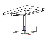
[spa_21], the base of the pittent-to-be
4.2 changing scale references
The next thing to do is to change the scale references. If needed, ofcours. In this case, the two "boxes" are both "square", or: the X-axis uses the same scale as the Y-axis. We don't need that for the lower box, but for the upper one, it's fine. So some scales need to be changed on the lower box. Easiest is to change the Y-values of the points of the lower box to the same scale as those of the upper box, so that the lower box gets as wide as the upper one. By pressing "show points numbers" on the object-toolbar, we see that the lower box consistes of vertices (0,1,2,3) and (4,5,6,7), whereby the 2nd four points are coupled to the first four. That means, we only have to change the lower 4 points, and the uper four go with that automatically. So change the Y-values of Point(0,1,2,3) to scale 2 by replacing "4"s with "8"s , and "132"s with "136"s.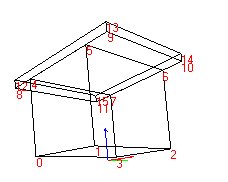
[spa_21_scales]
Now you see the basic form is OK.
4.3 changing scales
But the lower box is a little too fat. So just change scale0 from 343 to 64, gives it a much slimmer appearance.If you want to see the changes you made to the object instantanious, you just have to rotate the object slightly (click on the object and drag the mouse around). Because this scale value isn't being used anywhere else, the rest of the object is unchanged. Take note that changing a scale to zero can cause some unwanted side-effects (like a total crash), so better change a scale value to "very little", like 8, if you want for instance to make a pointed roof on this tent. As one unit on the scale of the objects is very small, the difference between zero and eight is negligeble anyway.This would also be a good time to inform you of the fact that 1024 object-units is exactly as long as one tracklengthunit, which is in turn 16 "real" feet, which is 4.87 meters. That makes one objectunit equal to 4.75 millimeters, or for those who haven't learned metric yet: 3/16th of an inch or (if you like) 1/337684th of a mile.
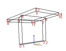
[spa_21_scales2]
4.4 changing heights
Only now the boxes do not attach properly anymore, because of the changes in the scales. You can adjust the heights of points(4,5,6,7) to make it look good. So now we have to do a little math to get the connection between the two "boxes" perfect. With some 1st grade math you get that ifZ-point(8)=730, and
Z-point(9)=891, then
Z-point(4)= (730+891)/2 - ((891-730)/2)*(64/558) = 801
Z-point(5)= (730+891)/2 + ((891-730)/2)*(64/558) = 820
The object looks like this after that:
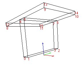
[spa_21_scales3]
Note how neatly the connection is done.... math is beautiful, isn't
it?
4.5 texture changing
As our object at this point still looks like a wooden shed, it's time for some new paint. I can't help you making good textures (just look at my tracks if you wonder why) so I can only tell you from the point onwards that this object is in your track and the JAM-IDs are all done. The JAM-tutorial will help you getting the textures and so on in your JAMs.You can look which entry in the texture data belongs to which polygone, by clicking on the "polygon numbers" button. It will put a number on all polygons and this number corresponds with the texture data. Somehow Paul still hasn't figured out it's impossible to read blue numbers on a blue background, so you'll have to rotate the object a little perhaps to read all numbers. You also need to rotate a little to see which number actually belongs to which polygon, as it's hard to see depths on a flat screen.
This might also be a good time to give you a tip about rotating the object: when you press the "ctrl" key while rotating the object, it gets rotated only by the Z-axis, while when you rotate without pressing "ctrl", it rotates the object around the X and Y axis.
Anyway, just change the number in the texture data to the ID# of the
texture you desire there. You can check whether all the textures you have
enteredfor that object are actually contained in the track, by clicking
on the "fill objects" and "texture map objects" buttons. An unknown texture-ID
is represented by a red/white blocked pattern.
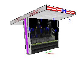
[spa_21_texs]
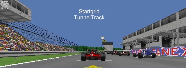
And now that the object is finished, you only need to place it in your track by changing one object description and placing this in the track with an 0x80 command. I
In the game, the pittents might look like this:
5. A few examples
In this section I plan to elaborate on some objects by giving step-by-step
instructions on how to go from the baseobject to the final thing. The covered
examples might include:
changed fly-over
people-adverts (as on TunnelTrack)
fence with top (as on TunnelTrack)
arc-bridge (as on TunnelTrack)
house with arcs (as on TunnelTrack)
castle (as on TunnelTrack)
pitbox (as on Zandvoort)
startlights (as on Zandvoort)
start"light" (as on TunnelTrack)
6. miscellanious:
undecided what will be in there, but the subjects might include:object 5s
bunch of trees
special properties of pitbuildings
visibility of anchors
lighting